Selecting the Right MOSFETs for Motor Drive Applications
Author: Siva Uppuluri, Applications Engineer
Automotive OEMs are migrating to BLDCs in order to maximize efficiency and reliability. This article looks at the important parameters engineers should consider during the design process, in order to meet these objectives.
The discovery of Electromagnetic Induction (EMI) changed the world and heralded in a new age. Today, it touches every sector, market and industry. The ability to generate electricity at will and convert that energy into motion with precise control and regularity is, in many ways, the hallmark of a developed society.
Electric generators and electric motors are, by far, the most common and widely deployed implementations of EMI. With the exception of solar power, the majority of useable electricity is created in this way, either by huge turbines in power stations or smaller generators in renewable solutions such as wind or wave.
In response to this abundance of energy, the generator’s counterpart, the motor, has successfully and inextricably displaced purely mechanical forms of motive force. The internal combustion engine is, perhaps, the latest step in this journey, as electric vehicles begin to proliferate our roads.
However, there is an intermediate step in the automotive industry’s move to electric power, and that is the replacement of mechanical devices with electric motors.
Increasing applications
From a consumer’s point of view, the most apparent use of electric motors in a vehicle might be to drive the electric windows and seats. Central locking is another application that could be cited. Under the hood, there’s a lot more change happening. Electric motors are gradually being specified over purely mechanical options for functions including fans, pumps (water, oil, fuel), power steering and anti‐lock braking, as well as automatic transmissions.
The reasons are clear; electric motors offer greater control, improved efficiency and higher reliability over mechanical alternatives. When the transition first began, OEMs turned to stepper motors and motors with brushed commutation but in more recent times the automotive industry — like many others — has migrated to brushless DC motors (BLDCs), and for good reason.
BLDCs offer even higher levels of efficiency, with better control over a wider dynamic range, as well as greater torque. And as the technology is brushless — effectively contactless, from an electrical point of view — it eliminates all of the electrical interference common with brushed DC motors. This helps lower electromagnetic interference, which can prove problematical to the more sensitive components in Engine Control Units (ECUs). It also avoids the arcing and subsequent wear common with brushed commutation, which can lead to a reduction in performance and eventual failure in a brushed DC motor.
Replacing mechanical motors with electrical alternatives does, of course, require additional control electronics. In the case of BLDCs this is, arguably, exacerbated by the lack of electrical contact. Controlling a BLDC is sometimes achieved through the use of Hall effect switches, which provide the necessary feedback for control loops. However, in more recent times, sensorless BLDCs have become popular, as removing the sensors further lowers the Bill of Materials.
The control algorithms developed to drive BLDCs (both with and without sensors) are ably handled by microcontrollers (MCUs), which offer the additional benefit of providing relatively simple integration to a vehicle network using CAN or LIN. MCUs designed for motor drive in an automotive application are also equipped with pre‐drive stages to control the MOSFETs needed to deliver the high drive currents through the motor’s coils. This final stage is critical in defining the efficiency of the overall motor drive solution, as described below.
Improved drive
The driver circuitry for a BLDC typically comprises MOSFETs to create and collapse electromagnetic fields created by stator coils, rotating around the rotor formed of a permanent magnet. Detecting the position of the stator is fundamental to generating the correct energising fields in the coils. In BLDCs that employ sensors it is the magnetic field that is detected, while in sensorless versions the control circuit measures back‐EMF to determine the stator position.
Either way, the coils are energized through MOSFETs arranged in a bridge topology. The selection of the MOSFETs is a major factor in the overall efficiency and performance of a BLDC; figures provided in datasheets are for use under specific conditions, which may or may not coincide with the operating conditions of the actual application. For this reason, it is essential to understand the application before selecting the most suitable MOSFETs.
Similarly, the operating parameters of the MOSFETs chosen will have a direct and significant impact on the total solution. Careful consideration of these parameters will ensure the MOSFETs selected best meet the requirements.
In general, there are three main areas that should be considered: reliability, efficiency and design. Reliability relates to the extreme limits of a device, and ensuring these limits are never tested during normal operation. Specifically, this relates to selecting a device with a breakdown voltage that provides sufficient protection against transients that may be introduced through other design choices. For example, for a BLDC operating from a 12V supply, a breakdown voltage of 40V would suffice. Similarly, in a 24V system, a MOSFET with a breakdown voltage of 60V would provide sufficient protection. It is also important to consider the drain‐to‐source current ratings, specifically under surge or pulse conditions. In a BLDC application, a start‐up or stall current could exceed the full load current by as much as three times, so a device with suitable drain‐to‐source surge/pulse current capabilities is advised.
In relation to MOSFETs, efficiency is generally an indication of how well a device manages heat dissipation, particularly at the junction. Good thermal design will always be necessary, especially in an environment with a high ambient temperature such as automotive, but there are several parameters that should be considered when selecting a MOSFET. These include the on‐resistance, Rds(on), and the gate charge (Qg). These two parameters are interrelated; a larger MOSFET can produce a low on‐resistance, but it can also result in a higher gate charge. This can have a significant impact on switching applications like BLDC drivers.
Temperature coefficients
Driving a BLDC with three phases (coils) is typically achieved by a PWM (pulse width modulated) signal generated by the MCU for energizing each of the phases. Figure 1 shows a typical bridge circuit for the phases of a BLDC. If both the MOSFETs are turned on at the same time, it results in a shoot‐through which will have catastrophic effects. To address this, a period will be designed into the PWM signals, known as Dead Time, which ensures only the intended MOSFET is conducting at any given time. The MOSFETs’ switching time will influence the length of Dead Time required, a parameter that is also affected by the gate charge of the device. During the Dead Time, the body diode of the MOSFET provides a commutation path, this is again not ideal due to the higher power losses with the diode’s conduction. Hence a good design works with the minimum possible Dead Time while avoiding any possibility for shoot‐through.
Each of the MOSFETs will exhibit a dynamic capacitance (Crss in Figure 1); this is a parameter that could result in a shoot‐through. This parameter in combination with the Rg, during switching, could result in the gate charge of the MOSFET on the low‐side rising to a level high enough to turn it on.
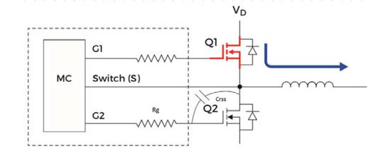
Figure 1. Typical bridge circuit for driving the phases of a BLDC motor
Another important parameter that should be considered for switching applications like BLDC drive is the zero temperature coefficient (ZTC) point. As shown in Figure 2, this is a point on the transfer curve (Drain current, [ID], vs Gate‐Source voltage, [VGS]). Operating a device below this point results in a positive temperature coefficient for the drain current, while operating a device above this point results in a negative temperature coefficient for the drain current. Figure 2a shows the transfer characteristics for a low‐density planar MOSFET (ZXM61N03F), Figure 2b shows the transfer characteristics for a high‐density planar MOSFET (ZXMN3A01E6). Generally, it is advisable to operate a device in the negative temperature coefficient region. The device featured in Figure 2b makes use of greater trench density to increase the number of vertical current flow paths in the channel. This has the positive effect of reducing Rds(on), although also results in a higher ZTC point.

Figure 2a (left). Low density planar MOSFET ZXM61N03F
Figure 2b (right). High density trench MOSFET ZXMN3A01E6
For a given size, an N‐channel MOSFET will typically feature an Rds(on) half that of the equivalent P‐channel device and for this reason it is common to specify N‐channel MOSFETs in motor drive applications. Figure 3 shows five stages of a full bridge motor drive circuit using N‐channel MOSFETs. It is important to note, also, that such circuits are subject to the effects of reverse recovery current flow due to the body diode of the MOSFETs. PWM algorithms that are able to minimize Dead Time can reduce these effects, while specifying MOSFETs with a fast recovery parallel diode is also advisable.

Figure 3. Circuit showing the commutation sequence and the body diode recovery related shoot through
Conclusion
Brushless DC motors are increasingly being specified by automotive OEMs. They offer greater efficiency, higher reliability and increased control in a widening number of functions, including replacing mechanical pumps and fans.
Driving a BLDC requires a combination of an advanced MCU for control, coupled with suitably specified MOSFETs to deliver the power. Thermal management lies at the heart of good design, and this extends to understanding how the unique requirements of BLDC drive circuits can be best met using the right MOSFET design.
By understanding and appreciating the pertinent parameters, engineers can select the right MOSFETs for the task, ensuring the highest reliability and efficiency in even the harshest environments.