Use a ReDriver™ or ReTimer for Longer and Thinner USB, USB Type-C, and DP Cables
USB, USB Type-C®, and DisplayPort™ (DP) cables have become so ubiquitous as to even be purchased in low-cost convenience stores. However, while two individual cables may appear identical to the naked eye, they can differ considerably in the quality of performance they provide. Low cost can mean low quality, and alongside instances where cheap cables have caused electronic equipment to malfunction or have corrupted data, they typically cause poor picture quality or slow down the rate of data transfer to well below the multi-gigabit bandwidth offered by the latest USB specification (USB 4).
Low-cost cables are usually passive: they do not use an external power source to transfer data. The quality of passive cables can be improved by constructing them using different metals, thicker shielding, and better connectors—but this approach is expensive and results in thicker, heavier cables. An alternative approach to improving cable performance is to make it active, i.e. powered, by embedding an integrated circuit (IC) that boosts the signal as it travels along the cable. Active cables offer several benefits—they provide better performance than even high-quality passive cables, and can be made thinner and longer. Thinner cables are more flexible and easier to manage, meaning they take up less space and do not inhibit the flow of cooling air at the rear of electronic equipment. In this article, we compare the performance of passive and active cables to show how to easy it can be to design an active cable.
Cable Specifications
The USB Implementers Forum (USB-IF) issues specifications for speed and wire types for USB and USB Type-C cable types. While it does not specify maximum cable lengths for the most recent generations of USB, the lengths shown in Table 1 are now generally accepted as standard values for the widely used USB, USB Type-C, and DisplayPort standards. As data rates increase, maximum cable length decreases, and this can be problematic if two devices are separated by a distance greater than the cable available to connect them. Even though cables can be joined (up to the supported cable standard’s maximum length), potential signal degradation necessitates using a powered hub to connect them, which may be impractical. Thus, it is preferable to use a longer cable that still meets the specification over its entire length.
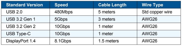
Table 1: Speeds and passive cable lengths for commonly used USB, USB Type-C, and DisplayPort standards
For USB 2.0, USB 3.2 Gen 1, USB 3.2 Gen 2, USB Type-C, and DisplayPort1.4, their specifications also define analog and digital parameters for impedance, skew, crosstalk, attenuation, differential impedance, bit error rate (BER), jitter, insertion loss, and more. Each parameter contributes to how well the cable provides a useful signal at the receiving end, and cable parameters have a significant impact on this ability.
Passive Cable Concerns
Long, thin, and low-cost cables are readily available, and while they may appear to function correctly, their performance dramatically impacts the quality of the signal they carry. Figure 1 shows a lab test set-up for a USB 3.2 Gen 1 cable performed at 5Gbps. A signal generator creates and measures a Rosenberger Cable Eye Test Configuration with the pattern PRBS 2E10-1 at 5Gbps (clocking at 2.5GHz). This test uses a three-meter (the maximum length permitted for USB 3.2 Gen 1) passive cable with a 96–104Ω differential impedance and -10dB insertion loss at 2.5GHz.
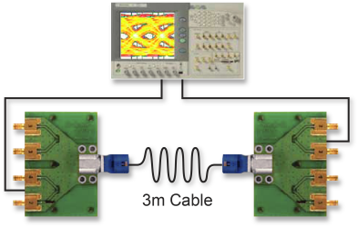
Figure 1: 2.5 GHz test set-up with a three-meter cable.
Figure 2 shows the eye diagram produced by this test. Firstly, it is evident that the eye regions are barely open, indicating that the performance of the cable would be poor in an actual application. Secondly, the colors show that the eye openings are small for lower BER (fewer errors per unit time). These results show that the USB 3.2 Gen 1 cable performs poorly at 3Gbps; the cable has a very high BER and will likely not meet accepted specifications.
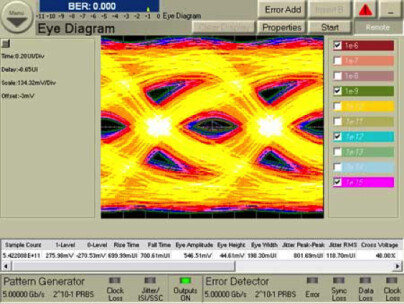
Figure 2: Eye diagram for passive three-meter USB 3.2 Gen 1 cable indicating a high BER
Making Cables Active
The solution to overcoming signal integrity challenges in USB, USB Type-C, and DP cables is to add a ReDriver or ReTimer at the cable’s source or receiving end.
A ReDriver is an analog amplifier that conditions the high-frequency (and differential) signals to widen eye openings. Some ReDriver ICs also perform line impedance matching, have programmable gain, and can help compensate for line loss, impedance mismatch, and other channel effects. One such ReDriver suitable for USB 3.2 Gen 1 applications is the PI3EQX7741AI by Diodes Incorporated. This two-channel 5.0Gbps device, shown in Figure 3, supports programmable equalization, de-emphasis, and output swing controls into two 100Ω differential CML data I/Os.
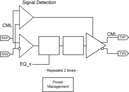
Figure 3: PI3EQX7741AI ReDriver by Diodes Incorporated
A ReTimer includes a clock and data recovery (CDR) circuit and automatically locks its internal clock to incoming data by detecting data-stream bit transactions. The CDR circuit reduces the output jitter by removing the jitter frequency from the PLL bandwidth. This allows the ReTimers, such as the PI2DPT1021 (shown in Figure 4) and PI2DPT821, to achieve good jitter performance in USB Type-C, USB 3.2 Gen 2, DP 1.4 Alt Mode, and pure DP 1.4 applications.
Diodes’ ReTimers also feature receiver adaptive equalization to address long-trace and short-trace applications. This function enables channel loss compensation up to -23dB for signal transmissions at 5GHz speeds and jitter cleaning, with no need for a local reference clock. A high-speed bidirectional channel is incorporated into the PI2DPT1021. It can be used for active cable implementations since both end connectors are the same and can act as a downstream-facing port (DFP) or upstream-facing port (UFP) as required.
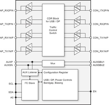
Figure 4: PI2DPT1021 ReTimer by Diodes Incorporated
The PI3EQX7741AI ReDriver can be used at the source or the receiving end of a USB 3.2 Gen 1 cable. Figure 5 shows two test scenarios for the same three-meter cable used previously. The ReDriver is placed at the receiving end (after the cable) in the left-hand image and at the transmitting end (before the cable) in the right-hand image.
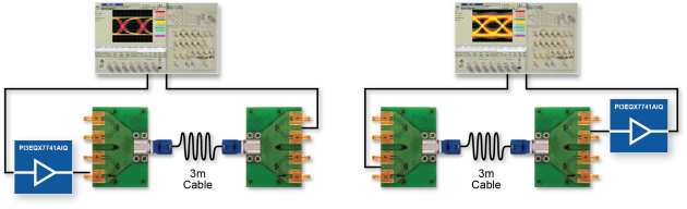
Figure 5: USB 3.2 Gen 1 ReDriver placed at the
receiving end (left) and the transmitting end (right) of an active USB 3.2 Gen 1 cable
The results of each test are shown in Figure 6. In each case, the ReDriver has dramatically widened the eye openings.
USB 3.0 Active Cable Configuration (2.5GHz, three meter)
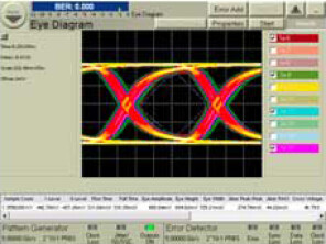
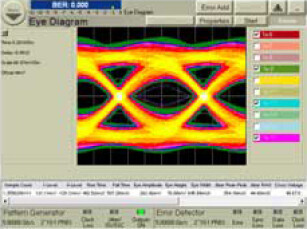
Figure 6: Eye diagrams for tests performed on active cable
Advantages of Active Cables
Active cables are constructed using ReDriver or ReTimer ICs and provide many advantages over passive ones. They can perform to a higher standard over longer distances, often exceeding recommended specifications. This is possible because ReDrivers like the PI3EQX7741AI and ReTimers like the PI2DPT1021 can compensate for signal attenuation, jitter, timing skew, crosstalk, and EMI. This allows active cables to be constructed using thinner and lower-cost materials, reducing their size. In turn, these thinner cables are easier to install in small spaces and allow better airflow around electronic equipment, allowing systems to run more efficiently at lower temperatures.
The Diodes logo is a registered trademark of Diodes Incorporated in the United States and other countries.
All other trademarks are the property of their respective owners.
© 2023 Copyright Diodes Incorporated. All Rights Reserved.