Diodes Incorporated

信号完整性 - ReDriver/ 信号中继器 / 调节器

Redriver,也称为讯号中继器(Repeater IC),可以重新产生讯号,在高速接口上增加讯号质量。高速的讯号频率造成设计上可用的宽裕度降低,增加设计耐用、高性能系统的难度。透过使用同等化(equalization)、预强调(pre-emphasis)和其他技术,可让单一ReDriver调整与矫正传输端上频道的损失,并在接收端上恢复讯号完整性。因此可以在接生端产生宽裕度足以满足传送可靠讯号、减少讯号错误率的眼图 。

redrivers application2

Redriver讯号中继器(Repeater IC)是解决设计复杂设计难题的关键的技术,现今各种应用的高速链接所需的高速数据传输通讯协议都可以应用。为了让更佳完善讯息能够在电路上传送,采用极佳的讯号调适技术,提供redrivers。Redrivers提供比基于协议讯号更好的性能,不需要在终端点终止信号,然后重新传送,因此消除延迟和附加系统成本。此外,redrivers调节与传递讯号是透过物理层工作,因此有极少的讯号抖动 。

Signal Integrity - ReDrivers/Repeaters/Signal Conditioners Details


Diodes ReDrivers address the five major issues negatively impacting the signal integrity of high-speed interfaces:

Signal Attenuation: High-speed signals, including differential signals, introduce noise and jitter that causes signal voltage swings to overshoot or undershoot the optimal eye opening.  This results in a degraded signal during high-speed signal switching.  

Signal Strength: Interfaces are increasingly being integrated into CPU chipsets.  While providing excellent performance in the lab, many of these chipsets are often not strong enough to provide reasonable design margin to meet compliance specs when designed into real-world systems with multi-layer boards, long traces, and extended cable lengths.


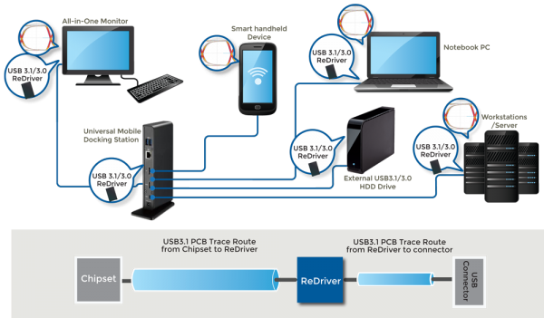
Signal Distance: Layout constraints, controller-to-connector separation, multiple PCB layers, vias, daughterboard connectors, and extensive cable lengths all contribute to signal distance and greater signal degradation.  For example, signal losses over FR4 PCB traces are typically 0.3dB per inch at 2.5 Gbps and 0.9 dB at 8 Gbps.


Noise: Both random and deterministic noise degrade signal integrity from a variety of sources, including crosstalk from other signals.  Another common source of random jitter is a noisy clock source that does not have good isolation or has impedance mismatches.

Lack of end-to-end control: When an interface connects to an external subsystem or device, designers do have not control over the signal distance, board vias, connectors, and cables over which the signal must still pass to reach its destination.  This can increase noise, jitter, attenuation, and insertion losses, and cause otherwise well-designed devices to fail to interface to equipment from other manufacturers.

The challenge for OEMs is that, as signal speeds increase, these factors become more pronounced, causing reliability, throughput, and quality to suffer.  To help developers maintain signal integrity, Diodes offers unparalleled signal conditioning technology with a comprehensive portfolio of devices for PCI Express, USB, Thunderbolt, SAS/SATA, Bluetooth, Wi-Fi, HDMI, and other popular standards.  Benefits include:

Superior Signal Quality: Diodes  ReDrivers have the lowest jitter and attenuation for the highest performance in the industry.  Comparative studies are available under NDA.

Lowest Crosstalk: By minimizing crosstalk, Diodes keeps channel-to-channel and part-to-part skew low.

Highly configurable: To provide developers greater flexibility, Diodes' ReDrivers can be configured on a per channel basis via an MCU over I2C rather than having to be pinstrapped or hardwired like other technologies.

Power Efficiency: These devices are architected for both low power operation and efficient power consumption.  For example, Diodes' SAS/SATA redrivers consume less than 100 mW per channel and have the best power efficiency on the market.

Multi-port: Diodes' redrivers support a variety of multi-channels configurations, providing flexibility while enabling greater integration and cost savings.  

Multi-protocol: Diodes' is the only manufacturer in the industry to offer a comprehensive portfolio of redrivers that work in both SATA and SAS environments.

Flexible packaging: Diodes' redrivers come in a variety of packaging options to meet the specific cost, performance, and power needs of your application.  With devices on the order of 4 mm x 4 mm, these redrivers can be placed close the interface connector to minimize signal losses.

Improving signal integrity increases the overall signal margin of systems.  OEMs can use this increased signal margin to:

  • Improve signal reliability and robustness
  • Increase the maximum trace distance and/or cable lengths over which signals can reliably be run
  • Reduce the number of board layers required to isolate signals effectively and substantially lower system cost
  • Ensure connectivity regardless of the quality of the external device to which a system is connected
  • Increase flexibility to simplify design, speed time-to-market, and reduce system cost by being able to use lower precision components elsewhere in the signal chain.

Diodes' is the market leader in redriver technology across applications, including networking, embedded computing, and communications, among others.  For example, in the server market, Diodes' was the first redriver manufacturer to achieve SATA3 compliance, and its technology has been adopted in more than 80% of server storage designs.  Diodes' redrivers are also part of many controller vendor reference designs, including Intel.  

As part of its commitment as the signal integrity leader, Diodes' offers unparalleled design support to its customers, including availability of evaluation boards, professional schematic and layout review, and system simulation to optimize the key opening using S-Parameter models, AMI-IBIS, or HSPICE.

High speed SAS 2.0, SATA 3.0, PCIe 2.0,PCIe 3.0, USB 3.0, DP 1.1 and DP 1.2

  • Increased signaling distance
  • Increased design flexibility
  • Standards compliance
  • Improved performance
  • Increased reliability
  • Reduced PCB & cable cost
  • Unique, differentiatted products to maximize the protocol's potential

Signal Integrity - ReDrivers/Repeaters/Signal Conditioners FAQs

Are Pericom PCIe 3.0 ReDrivers™ compatible with PCIe 1.0 & 2.0?

Yes, Pericom 3.0 ReDrivers PI3EQX8908A2, can be used in PCIe 1.0 and 2.0 modes.

Does Pericom PCIe ReDriver™ include a PCIe CLK buffer?

Pericom PCIe 1.0 ReDriver™ does include a PCIe CLK buffer but neither the PCIe 2.0 nor 3.0 ReDriver includes a
PCIe CLK buffer.

Does Pericom provide PCIe ReDriver's™ simulation model and reference circuit?

Yes,  Please contact your sales representative for simulation model and reference circuit. or contact Pericom Customer Support.

How do I know the PCIe ReDriver™ is already linked up with the CML output device?

Our PCIe 3.0 ReDriver can perform output (ReDriver's TX) side 50-Ohm termination detect. The ReDriver's RX50 pin is asserted high once the device detects the 50-Ohm termination.


How do I know the PCIe ReDriver™ is working and signal is passing through the ReDriver IC?

The PCIe ReDriver provides the signal output pin, "SIG", to indicate that signal is passing through the ReDriver.

How long can the PCB trace extend using a Pericom USB3.0 ReDriver™?

Pericom PI3EQX7701 EQ can compensate 5 db and 11db loss (2.5 GHz or 5 Gb/s).

How long the PCB trace can extend using a Pericom PCIe ReDriver™?

Please refer the AN233, page 5 and page 9.

Is Pericom's USB3.0 ReDriver™ compatible with USB2.0?

No. USB 3.0 uses different connect pins from USB 2.0's. The USB 3.0 Standard-B receptacle interfaces are divided into two sets of interfaces: the USB 2.0 interface and the USB 3.0 SuperSpeed interface. The USB 2.0 interface is comprised of pins 1 to 4, and the USB 3.0 SuperSpeed interface is comprised of pins 5 to 9. The figure below shows  the footprint of USB3.0 found in "Universal Serial Bus 3.0 Specification Version 1.0_Page 5-19_Figure5-8".

Is there a replacement for an obsolete part?

Not all obsolete parts will have a direct replacement. However, we recommended that you contact your regional sales office.

Is there any Application Notes for PCIe ReDrivers™?

Yes, AN088 and AN233 are Application Notes for PCIe ReDrivers.

Is there any pull up/down resistor needed on Dual Mode DP Source Device on Pin 13 of cable adaptor detect?

1Mohm pull down resistor on Pin 13 is needed on Dual Mode DP Source Device.

What are the types of jitter?

There are several types of jitter, but the main ones are: cycle-to-cycle jitter, period jitter, half period jitter, and peak-to-peak jitter. Jitter terminology can be found in AB36: Jitter Measurement Techniques at Application Brief No. 36 or Application Note No. 27.

What controls are provided by the PCIe ReDriver™?

Both I2C and GPIO controls are provided.

What does de-emphasis control mean?

Emphasis control can improve USB3.0 ReDriver's output signal.
The integrated de-emphasis circuitry provides flexibility and improves the integrity of USB3.0 output signal after ReDriver.
The de-emphasis selection table below describes pin strapping options and associated de-emphasis operations. This table can be found in  datasheet, page 3.

What does emphasis control mean?

Emphasis control improves the PCIe ReDriver output signal.

What does EQ control mean?

EQ control can improve the USB3.0 ReDriver's input signal. The integrated equalization circuitry provides flexibility and improves the integrity of the USB3.0 input signal before the ReDriver. The Equalizer Selection table below describes pin strapping options and associated operations of the equalizer. This table can be found in PI3EQX7741AI datasheet, page 3.

What does swing control mean?

Swing control can adjust the ReDriver IC output swing level.

What is cycle-to-cycle jitter?

Cycle-to-cycle jitter is the difference in the clock's period between two consecutive cycles and is expressed in units of + pico-seconds. This is because it can be either leading or lagging from the ideal output waveform.

What is the application suitability comparison between a switch and a logic driver?

A switch is a passive device with C-on and R-on that will attenuate the signal. A logic driver is an active device that will refresh an input signal at output by its active driving ability. Thus, compared to a logic driver, the maximum frequency of an application using a switch is limited by the trace length and the capacitive load. It is recommended to use a logic driver for applications with heavy capacitive load, long trace and high frequency.

What is the impedance range for USB3.0?

The range of the impedance is from 75Ω to 105Ω.

What is the lead finish for Pericom products? What about lead-free?

All Pericom's products that are not lead-free are composed of 85% Sn and 15% Pb. For lead-free products, they are composed of 100% matte Sn. Lead-free products are marked and ordered with the letter "E" suffix at the end of the part number.

What is the minimum input swing level that a Pericom PCIe ReDriver can accept?

The minimum input swing level is shown in the specification "CML input Differential Input Peak-to-peak Voltage" and some ReDrivers can automatically select the input threshold voltage.

What is the significance of the EQ control?

EQ control can improve the PCIe ReDriver input signal.

When the client-side returns a feedback packet to the host side, will Pericom's PCIe ReDriver block the packet or require control?

No, Pericom PCIe ReDriver will not block any PCIe signals. The ReDriver only enhances gains of the data voltage without changing the data. The host always sees the end-point directly. Pericom ReDriver is "100% transparent", which means the "host" and "end-point" do not detect the presence of the ReDriver.

Where can I find Mean Time Before Failure (MTBF) or Failures In Time (FIT) values for Pericom products?

FIT and MTBF data can be found at Pericom's Quality webpage.

Where can I find the information on your Pb-free and "Green" packaging?

Lead (Pb)-Free and Green information can be found on individual datasheets or Pb-Free & Green Page.