Simplify Your Embedded Designs Using I²C I/O Expanders
The two-wire I²C bus is a flexible way to add many different types of low-speed I/O while also simplifying designs and trace routing.
The I²C two-wire bus is still as popular today as when Philips originally invented it in 1982. Initially operating at 100KHz, the latest incarnation, version 7 (2021) Ultra-Fast-mode (UFm), now clocks at 5MHz—making it fast enough for most medium-speed peripherals, including digital I/O, GPIO, keyboards, keypads, and sensors. I²C is an ideal way to transport signals around many embedded systems, including smartphones or those destined to live on the “cloud edge” of the Internet of Things (IoT). This article reviews how I²C, as a design tool, can add value to your embedded designs.
Two Wires; Too Easy
I²C’s multi-drop, 3.3V or 5.0V active low, two-wire interface is easy to configure and program. Using a Serial Data Line (SDA) and Serial Clock Line (SCL), a master device controls the bus while slave devices acknowledge their 7- or 10-bit address (Figure 1). Communication by the master device ends with the transmission of a stop bit. There can be several masters, and the number of slaves is only limited by the available addresses and bus capacitance.
Especially since, in practice, most I²C lines are located on a single PCB, the length of a typical I²C bus is in the order of several meters, which is sufficient for on-board or board-to-board system communications. The I²C protocol uses a combination of START and STOP bits, typically enumerated by dropping lines from a high voltage to a low voltage (high being 5VDC or 3.3VDC).
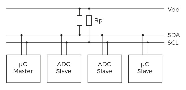
Figure 1: I²C uses a Master/Slave, two-wire bus with pull-ups to an active high state.
I²C Simplifies Pinout, Fanout
Requiring only a single supply and two easy-to-route lines, I²C can be easily adapted to communicate with many other medium-speed interfaces such as GPIO, A/D/A, and level shifters, and thus used for communication with many different types of IoT sensors. Many devices and interface types can be multiplexed, converted, and transported using I²C. For example, a wide parallel interface can be reduced to a two-line I²C, reducing the number of wires and traces and thereby decreasing overall routing complexity. It is always important to make the most efficient use of I/O pins on SoCs, and I2C is ideal for this purpose. For example, all the devices shown in Figure 2 can communicate with an SoC using only two pins, while an I²C bridge can enable two-pin communication with an SPI bus or a UART.
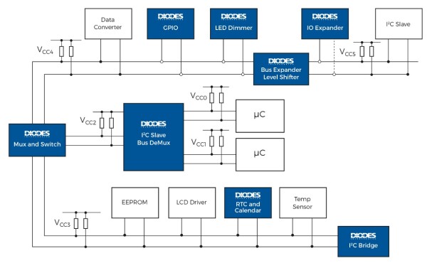
Figure 2: I²C can also be used to communicate with sensors and medium-speed interfaces.
I²C is now fast enough to accommodate bidirectional I²C multiplexers that run multi-trace signals (or busses) over a longer distance, using only two wires (shown in Figure 3). Converting from a wide parallel bus to I²C saves on PCB routing and allows for cheaper (and simpler) connectors to be used. I²C can even act as a bus extender between boards in a system.
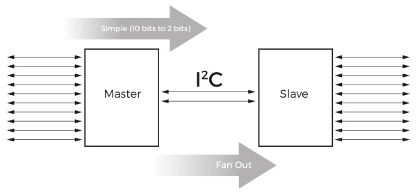
Figure 3: Using I²C to extend and/or simplify a parallel bus.
Figure 4 shows an I/O expander that converts an I²C bus to a 16-bit parallel bus. The PI4IOE5V9539 is I²C compliant and supports active low signaling, 400KHz fast-mode operation for dual-simplex (all input or all output) GPIO operation, and can clock up to 2MHz if needed. The device can be combined with three others to create a 48-bit parallel data bus connecting to a two-wire I²C interface (using four I²C slaves). This is equivalent to a 48-wire keypad controller converting to two I²C wires using only four tiny, 24-pin, TSOP parallel I/O expanders.
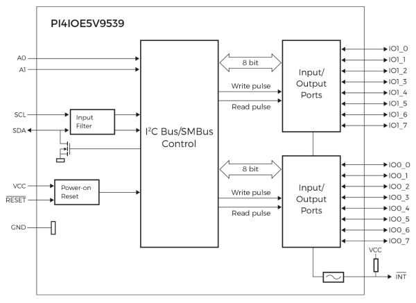
Figure 4: Block diagram for a 16-bit I²C-to-GPIO expander.
Don’t Wake Me
Another reason I²C I/O expanders are so helpful is that they add local line control, which frees up the system controller from handling low-level tasks. In the simplified cell phone block diagram shown in Figure 5, the baseband/application engine is not required to constantly poll the I/O blocks (which wastes battery power by keeping the controller awake). Instead, the INT (interrupt) output line wakes up the controller only when necessary, allowing it to save power in standby or sleep mode—an essential requirement for battery-operated devices.
The I/O expander in Figure 4 also has a RESET feature. By setting the default values at power-on without the requirement to cycle device power, the powered-up system returns to a known ‘good’ state. The polarity of the device can also be conveniently switched between input and output for bidirectional operation.
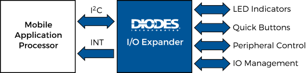
Figure 5: The expander’s interrupt line (INT) means the Mobile Application Processor can stay in idle or sleep mode for longer.
Little Tricks to Simplify Designs
I²C I/O expanders also simplify system designs in other, less obvious ways. Diodes Incorporated’s I/O expander product line has multiple fanout options (x2, x4, x8 x16, up to x48) and more sophisticated features. For example, a 1.65V to 5.5V supply range (Vcc) provides designers with a choice of voltage levels, from typical 5.0 VDC TTL down to the lower voltage levels used in battery and mobile devices.
I²C is simple and robust, but noise can become a problem as traces become longer. Adding noise filtering on the I²C SCL and SDA lines prevents false level changes. Some I/O expanders also support TTL and CMOS voltage levels on the I²C lines, providing a convenient feature for legacy designs.
The PI4IOE5V6408, shown in Figure 6, is an 8-bit general-purpose I/O expander that provides remote I/O expansion for most microcontroller families via the I2C-bus interface. This keeps interconnections to a minimum where additional I/Os are required, such as in battery-powered mobile applications that interface to sensors, push buttons, and keypads. It operates from 1.65V to 4V on the GPIO-port side and 1.65V to 3.6V on the SDA/SCL side. This allows the PI4IOE5V6408 to interface with next-generation microprocessors and microcontrollers on the SDA/SCL side, where supply levels are reduced to save power.
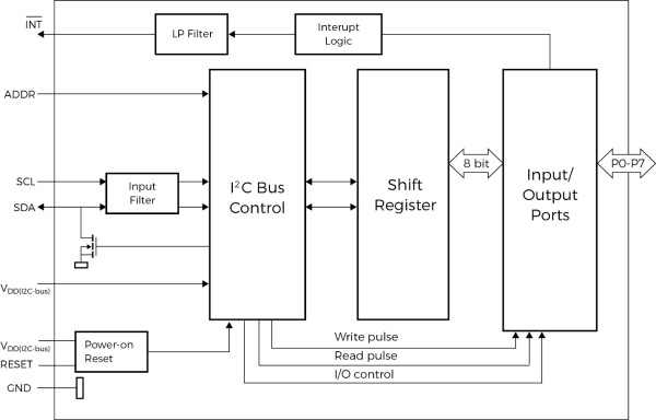
Figure 6: This 8-bit I²C I/O expander can operate at 1MHz.
From Two to Too Many to Count
In this article, we have shown how I²C I/O expanders can benefit embedded designs. Fan out/in, saving SoC power consumption, reducing pin usage, and directly driving LEDs are some of the ways an I²C I/O expander can be cleverly used in conjunction with the more mature I²C bus. The number of possible applications for I²C expanders is countless, and we invite you to explore these in your designs.