Battery-Discharge Protection for Appliances on the Move
Safety Isolation in Cordless Appliances
With the growing popularity of cordless appliances for use in the home and industry, there is a new demand for battery-discharge protection. Two prime examples are autonomous lawn mowers and vacuum cleaners that return to a docking station for charging or when not being used.
The connection to the charger is usually made by aligning a pair of metal charging contacts on the appliance with corresponding contacts on the charger. These contacts are often located on the underside of the appliance, which brings a risk of a short circuit occurring if the appliance passes over an exposed metal item. A vacuum cleaner may cross a carpet joiner, or a lawnmower may encounter unexpected types of metallic objects hidden in grass.
Operational safety for unattended autonomous appliances therefore becomes an important consideration, as a short circuit occurring across the charging terminals could result in potentially very high battery discharge currents.
Battery-Discharge Protection
There are various ways of protecting the charging contacts against the risk of a short circuit. A protective flap or door could be implemented to move across and provide cover as the appliance disconnects from the charger, or the contacts could be made to retract. However, designing such a mechanism adds extra expense and a cover may break or malfunction. Similarly, a mechanically operated switch could be inserted in the circuit to isolate the contacts automatically when the appliance detaches from the charger.
An electronic protection circuit contains no moving parts and offers a more robust and reliable solution. One option that could be implemented is by using a straightforward diode arrangement. However, the voltage drop across the diode when forward biased leads to a reduced charging voltage being delivered to the battery, resulting in undesired power dissipation.
A diode rectifier with a typical forward voltage VF =0.55V carrying a 3A charging current would dissipate 1.65W (P=I x VF).
Some appliance makers seek to overcome this by implementing reverse-discharge protection using a MOSFET. When turned on during charging, the MOSFET’s low on-resistance (RDS(on)) ensures minimal reduction in the applied charging voltage, thereby helping ensure optimum charging and battery runtime. In addition, power dissipation is minimized.
A P-type MOSFET (such as the DMP4047LFDE), which has an RDS(on) of 33mΩ, reduces the battery charging voltage by only 99mV and significantly lowers the power dissipation to 0.297W (P=I2 x R).
Ideal Diode Controller
The DZDH0401DW from Diodes Incorporated simplifies designing the circuitry needed to control the MOSFET. The device is an ideal diode controller designed in a compact SOT363 package that measures just 2.15mm x 2.1mm x 1mm. This small form factor helps engineers meet the tight space constraints inside equipment including cordless appliances and small power tools. It can also be used in redundant and hot-swappable power supplies and general high-side gate driving to provide high-side disconnect switch solutions.
The DZDH0401DW is suited to systems operating at up to 40V and drives a P-channel MOSFET to emulate an ideal diode. It operates as a differential amplifier and PMOS controller to minimize forward current losses when the voltage sensed at the input is greater than that at the output. Conversely, it provides high isolation when the sensed input voltage is less than the output.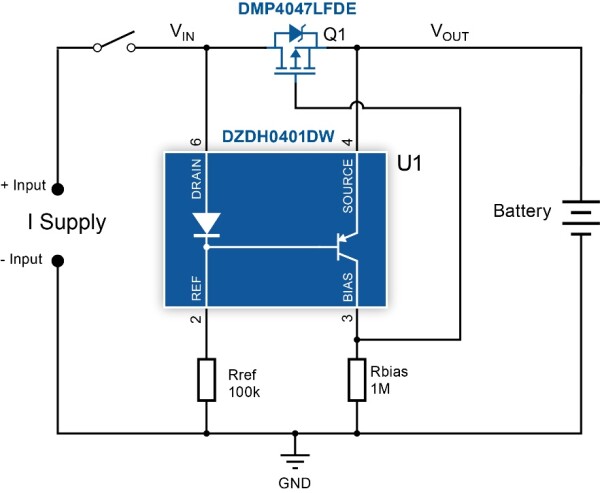
Figure 1. Appliance battery-discharge protection circuit.
Figure 1 shows an application circuit for battery-discharge protection in a cordless appliance. When the supply is connected, the body diode of MOSFET (Q1) becomes forward biased. The DZDH0401DW internal drain diode holds the base of the integrated PNP bipolar transistor at VIN – VF(DIODE), resulting in not enough VBE for the transistor to turn on. As the gate capacitance of Q1 charges through the externally connected resistor, Rbias, Q1 turns on and its RDS decreases—causing VDS to also decrease. Consequently, VBE across the transistor rises and the transistor starts to conduct. When Q1 RDS reaches its lowest value, (RDS(on)), VBE at the integrated transistor is at its highest and IC is at the maximum VGS should be high enough to ensure linear operation.
Rref and Rbias set the currents through the drain diode and integrated transistor’s collector respectively, so that VF(DIODE) is greater than VBE(on). Rbias determines the turn-on speed of the MOSFET. When the ideal diode circuit is turning on, the internal transistor is held off by the drain diode and the MOSFET voltage drops. Rbias pulls the gate low and turns on the MOSFET. The resistors’ values are chosen to minimize quiescent current operation of the circuit.
When the supply is disconnected, the input voltage is removed and VDS becomes less than the turn-off threshold voltage (VT) of the controller. Since Q1 is still on, node VIN is the same as VOUT from the battery. This causes the voltage drop in Rref, VREF, to fall. As the internal transistor is on, Q1 gate capacitance discharges through it and the MOSFET turns off, providing high isolation between input and output. The value of Rref sets the turn-off speed of the MOSFET. A lower resistance value increases the base drive to the transistor, so that the transistor shorts out the gate more quickly to turn off the MOSFET.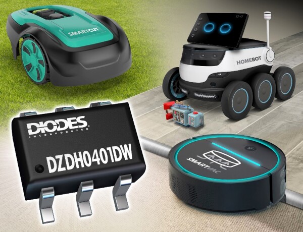
Figure 2. New demand for battery-discharge protection within the design of autonomous lawn mowers and vacuum cleaners.
Conclusion
A MOSFET having low on-resistance (RDS(on)), controlled as an ideal diode, can be used effectively for battery-discharge protection in consumer appliances—having long been the device of choice for reverse-current protection and power OR-ing circuitry. A simple single-chip controller simplifies the implementation, helping to save space, improve battery performance, and increase energy efficiency.
The Diodes logo is a registered trademark of Diodes Incorporated in the United States and other countries.
All other trademarks are the property of their respective owners.
© 2024 Diodes Incorporated. All Rights Reserved.
This article originally appeared in New Electronics (UK) on November, 2023.