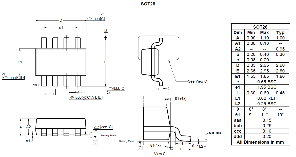
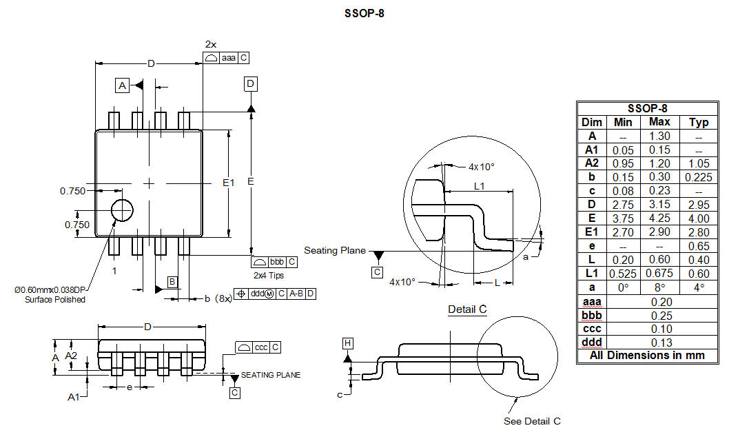
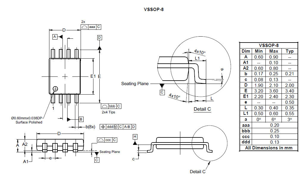
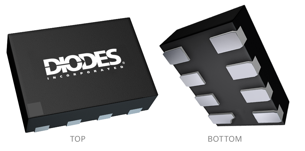
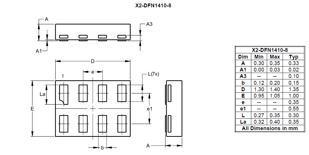
Diodes Incorporated
Back to Universal Level Shifter / Voltage Translation (ULS)

PI6ULS5V9306

Dual Bi-Directional I2C-bus and SMBus Voltage-Level Translator

Contact Sales

Log in or register to manage email notifications about changes to datasheets or PCNs for this part.

Product Description

The PI6ULS5V9306 is a dual bidirectional I2C-bus and SMBus voltage-level translator with an enable (EN) input, and is operational from 1.0 V to 3.3 V (VREF1) and 1.8 V to 5.5 V(VREF2).

The PI6ULS5V9306 allows bidirectional voltage translations between 1.0 V and 5 V without the use of a direction pin. The low ON-state resistance (Ron) of the switch allows connections to be made with minimal propagation delay. When EN is HIGH, the translator switch is on, and the SCL1 and SDA1 I/O are connected to the SCL2 and SDA2 I/O respectively, allowing bidirectional data flow between ports. When EN is LOW, the translator switch is off, and a high-impedance state exists between ports.

The PI6ULS5V9306 is not a bus buffer that provides both level translation and physically isolates to either side of the bus when both sides are connected. The PI6ULS5V9306 only isolates both sides when the device is disabled and provides voltage level translation when active. The PI6ULS5V9306 can also be used to run two buses, one at 400 kHz operating frequency and the other at 100 kHz operating frequency. If the two buses are operating at different frequencies, the 100 kHz bus must be isolated when the 400 kHz operation of the other bus is required. If the master is running at 400 kHz, the maximum system operating frequency may be less than 400 kHz because of the delays added by the translator.

As with the standard I2C-bus system, pull-up resistors are required to provide the logic HIGH levels on the translator’s bus. The PI6ULS5V9306 has a standard open-collector configuration of the I2C-bus. The size of these pull-up resistors depends on the system, but each side of the translator must have a pull-up resistor. The device is designed to work with Standardmode, Fast-mode and Fast mode Plus I2C-bus devices in addition to SMBus devices. When the SDA1 or SDA2 port is LOW, the clamp is in the ON-state and a low resistance connection exists between the SDA1 and SDA2 ports. When the higher voltage is on the SDA2 port, and the SDA2 port is HIGH , the voltage on the SDA1 port is limited to the voltage set by VREF1.

When the SDA1 port is HIGH, the SDA2 port is pulled to the drain pull-up supply voltage (VDPU) by the pull-up resistors. This functionality allows a seamless translation between higher and lower voltages selected by the user without the need for directional control. The SCL1/SCL2 channel also functions as the SDA1/SDA2 channel.

All channels have the same electrical characteristics and there is minimal deviation from one output to another in voltage or propagation delay. This is a benefit over discrete transistor voltage translation solutions, since the fabrication of the switch is symmetrical. The translator provides excellent ESD protection to lower voltage devices, and at the same time protects less ESDresistant devices.

Features

  • 2-bit bidirectional translator for SDA and SCL lines in mixed-mode I2C-bus applications
  • Standard-mode, Fast-mode, and Fast-mode Plus I2C-bus and SMBus compatible
  • Less than 1.5 ns maximum propagation delay to accommodate Standard mode and Fast mode I2Cbus devices and multiple masters
  • Allows voltage level translation between:
    • 0.9V VREF1 and 1.8 V, 2.5 V, 3.3 V or 5 V VREF2
    • 1.2 V VREF1 and 1.8 V, 2.5 V, 3.3 V or 5 V VREF2
    • 1.5 V VREF1 and 2.5 V, 3.3 V or 5 V VREF2
    • 1.8 V VREF1 and 3.3 V or 5 V VREF2
    • 2.5 V VREF1 and 5 V VREF2
    • 3.3 V VREF1 and 5 V VREF2
  • Provides bidirectional voltage translation with no direction pin
  • Low 3.5 ohm -state connection between input and output ports provides less signal distortion
  • Open-drain I2C-bus I/O ports (SCL1, SDA1, SCL2 and SDA2)
  • 5 V tolerant I2C-bus I/O ports to support mixed mode signal operation
  • High-impedance SCL1, SDA1, SCL2 and SDA2 pins for EN = LOW
  • Lock-up free operation for isolation when EN = LOW
  • Flow through pin out for ease of printed-circuit board trace routing
  • ESD protection exceeds 4KV HBM per JESD22- A114
  • Package: TDFN2x3-8L, MSOP-8L,SOIC-8L

Product Specifications

Product Parameters

Compliance (Only Automotive supports PPAP) Standard
Translation From (V) 1.2 to 3.3
Translation To (V) 1.8 to 5
Max Signal Rate 400kHz
Bits Needed 2
Auto Direction Sensing? Yes
Shift Bi-Directional
Prop Delay N/A
Ambient or Junction Temperature (°C) -40 to 85

Technical Documents

Recommended Soldering Techniques

TN1.pdf

Additional Technical Documents are available upon request:
Application information, Evaluation board, and Other technical documents

Request Documents

Product Change Notices (PCNs)

A PCN may only apply to specific orderable part numbers in this datasheet. Please refer to the corresponding PCN to see the exact orderable part number(s) affected.

PCN # Issue Date Implementation Date Subject
PCN-2602 2023-01-31 2023-07-31 Device End of Life (EOL)
PCN-2510 2021-02-26 2021-05-26 Qualified Additional A/T Sites, Fab Site and Data Sheet Change
PCN-2505 2021-01-26 2021-07-26 Device End of Life (EOL)
PCN-2493 2020-12-28 2021-03-28 Qualified Additional A/T Sites and Bill of Materials (BOM)

FAQs

Related Collection FAQs