
Revolutionizing Industrial Power Supply: The ZXCT21x Series Unveils a New Era of Precision and Efficiency
By Steve Hsiao, WW Strategic Technical Marketing
In the rapidly evolving landscape of industrial power supplies and the USB Power Delivery (PD) 3.0 Standard, the need for accurate, efficient, and reliable current sensing solutions has never been more critical. Enter the ZXCT21x series—a new lineup of dedicated current sense amplifiers designed to transform how engineers approach current measurement in applications ranging from laptops and docking stations to portable chargers. This article explores the common challenges faced in current sensing, the limitations of traditional discrete component solutions, and how the ZXCT21x series emerges as a superior alternative, promising to streamline the design process and significantly enhance system performance across a spectrum of industrial and consumer applications.
The ZXCT21x devices are for power rails below 26V, with high-side or low-side sensing for both uni- and bi-directional applications. Target applications include battery management systems for measuring charge and discharge currents in batteries, monitoring the average current of a motor for speed control and protection, monitoring the output current of a power supply for regulation and overload protection, measuring the panel current to enhance solar power system performance, monitoring currents in various industrial automation equipment for control and diagnostics, measuring battery drain current, and optimizing power usage of portable electronic devices.
With discrete components, it is not easy to achieve the same level of accuracy as dedicated current sense amplifiers such as the ZXCT21x. The circuit design becomes more complex, requiring several passive components and careful op amp selections to meet the desired gain, bandwidth, and common-mode rejection ratio (CMRR) (see Figure 1).
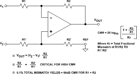
Figure 1. Component selection, calibration, and performance are important considerations for discrete solutions
In a typical discrete circuit, which uses four gain resistors and an op amp, you would need to match the resistor tolerances. Adding further complexity, discrete solutions often require manual calibration to compensate for component variations and drifts. Also, as input op amp offset voltage varies with temperature, dealing with offset drift becomes challenging, negatively impacting accuracy. In addition, discrete components might offer a different level of performance than a dedicated current sense amplifier—such as the ZXCT21x—in terms of noise, offset voltage, and power consumption.
Using dedicated current sense amplifiers offers several advantages. The ZXCT21x series simplifies current sensing circuitry—the devices are easy to use and require minimal external components. The ZXCT21x is designed specifically for current measurement and achieves high accuracy due to careful calibration and internal compensation techniques. Compared to discrete solutions, they offer good noise performance, low offset voltage, and low power consumption. More importantly, while discrete components might seem cheaper initially, the costs of design complexity, calibration efforts, and potential performance compromises outweigh the savings.
However, the ZXCT21x should only be considered for high-side sensing of power rails below 26V, due to the 26V common-mode voltage (VCM(max)) limitation. Conversely, the negative voltage sense should be higher than -0.3V due to its VCM(min) limitation. The device should also not be considered for monitoring a dynamic switching current from an inductive load due to its limited bandwidth of 4kHz to 80kHz.
The maximum current that the ZXCT21x can measure depends on Ohm’s law; for example, with an Isens of 100A and Rsens of 0.1Ω, the maximum Vsens would be 10mV. The current measurement resolution is dependent on the gain selected—50, 75, 100, 200, 500, or 1000—and the reference voltage (Vref). As a general rule, the lower the gain, the higher the resolution, but the output voltage is lower. Hence, when you are designing the circuit, you must consider the trade-off between the resolution and dynamic range.
The ZXCT21x operates on a single supply between 2.6V and 26V and its maximum output voltage is the same as the supply voltage. To minimize noise, ensure that you have good power supply filtering and proper grounding. Here, grounding is crucial for accurate measurements, therefore, use a common ground plane and connect the ground (GND) pin to a low-impedance ground.
In general, the ZXCT21x does not need calibration as it is a high-precision device with only 100µV offset voltage and maximum gain error of 0.8%. The ZXCT21x has a zero-drift core to offer only 0.5μV/°C input offset drift across the full operating temperature range from -40°C to +125°C. Outside this temperature range, the accuracy may drift slightly so consider temperature compensation, if needed. However, regarding the system design, especially at high currents or wide temperature ranges, manual calibration can be performed in factory mode. By using an on-board microcontroller (MCU), calibrate the offset voltage and gain error as close to zero as possible for optimal accuracy.
In addition, PCB layout considerations are critical for success. Keep the high-current traces away from sensitive analog circuitry, use proper bypassing and filtering capacitors, and minimize trace resistance and inductance. Based on your application's requirements, there are also protection features to consider, such as reverse current protection, overcurrent protection, and ESD protection.
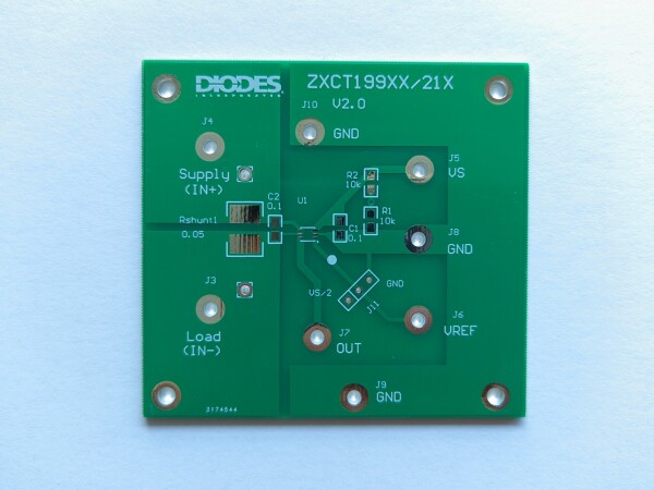
Figure 2. Demonstration board overview of the ZXCT21x
To support your next designs, Diodes Incorporated (Diodes) provides free evaluation boards and technical services, including application notes. The demonstration board, shown in Figure 2, includes one SOT363-packaged ZXCT21x, a decoupling capacitor at the power supply end, an interference suppression capacitor at the input end, two voltage divider resistors for selecting VREF, one selector for connecting different voltages to the VREF terminal, and six test point connectors (R3 and R4 omitted).
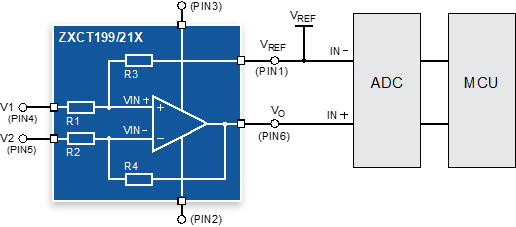
Figure 3. Recommended application circuit where the ADC’s in-pin is connected to the MCU’s ground pin
In common applications, the circuit shown in Figure 3 is often used. Here, the ADC’s in-pin is connected to the MCU’s ground pin. This circuit has the advantage that the ADC input voltage is always equal to (V1.0-V2.0) × gain, regardless of how the VREF pin is connected. This means that only one measurement is needed to obtain the desired data, which reduces the workload of the ADC and MCU and improves efficiency.
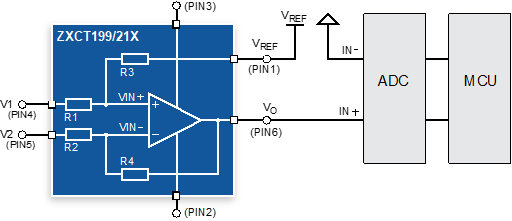
Figure 4: ZXCT21x application circuit diagram used less often
In contrast, the circuit shown in Figure 4 requires the measured data to be subtracted from VREF, and this VREF value must either be set in advance or measured separately. This increases the workload of the MCU. Typically, the power supply voltage for the ZXCT21X is set to 5V or 3.3V, and the input voltage range of the ADC is 0V~5V or 0V~3.3V, respectively. Since the ADC and MCU must have compatible voltage levels, it may be necessary to use a level-shifter circuit to convert the signals between the two devices if they operate at different voltages. If there is interference, filters should be added to the input and output sections as necessary to filter out the interference signals and improve stability.
To measure bi-directional symmetric current, set the VREF voltage to half of the supply voltage. For uni-directional positive current, set the VREF voltage to 0.5V (or 0.2V, etc.). This will give the output voltage a range of 0.5V to 4.5V (or 0.2V to 4.8V). At zero current, the output voltage will be equal to VREF. At maximum current, the output voltage will be at its highest value, which increases the dynamic range of the output voltage.
Similarly, to measure uni-directional negative current, set the VREF voltage to 4.5V (or 4.8V, etc.), which will give the output voltage a range of 0.5V to 4.5V (or 0.2V to 4.8V). At maximum current, the output voltage will be equal to VREF. At minimum current, the output voltage will be at its lowest value, which also increases the dynamic range of the output voltage.
In conclusion, the ZXCT21x series presents a compelling solution for current sensing needs in a variety of applications, particularly in the realms of industrial power supplies (12V/24V) and the USB PD 3.0 Standard (5/9/15/20V) for devices such as laptops, docking stations, and portable chargers. The series addresses common challenges associated with current sensing, offering a streamlined alternative to complex and less accurate discrete component solutions.
While discrete components may initially seem cost-effective, the additional design complexities, calibration efforts, and potential performance compromises can ultimately lead to higher overall costs and inferior system performance. By eliminating the need for manual calibration and complex component matching, the ZXCT21x series not only simplifies the design process but also enhances the overall accuracy, efficiency, and reliability of the system.
However, it's important to note the limitations of the ZXCT21x series, including its common-mode voltage range and bandwidth constraints, which may render it unsuitable for certain applications. Despite these limitations, the series excels in a wide range of applications, from battery management systems to industrial automation equipment, offering a versatile solution for current measurement and monitoring.
The Diodes logo is a registered trademark of Diodes Incorporated in the United States and other countries.
All other trademarks are the property of their respective owners.
© 2025 Diodes Incorporated. All Rights Reserved.
This article originally appeared in the Dec-Jan issue of Electronics for Engineers (UK).