Single-chip Solutions Make Adding Battery Management Simpler
Author: Khagendra Thapa, SPM BU Director
A range of battery protection devices provides an easy and affordable way for OEMs to improve product safety and integrity.
From cell phones to wearable technology, there is a growing number of portable devices entering the market. Although different in design, they all share common features, most notably they are (normally) powered by a rechargeable battery, which is (normally) a single-cell. The continued evolution of integrated devices means they are becoming both physically smaller and lower power, meaning they are able to be powered for longer from a smaller battery. However, this puts pressure on device manufacturers to ensure their designs don’t sacrifice good design practices in favor of smaller form-factors.
It is still rare but not unknown for portable devices to suffer from battery malfunctions, which can lead to catastrophic and potentially hazardous failure. The cause of these failures may not be fully disclosed but it is clear that the source of the heat behind the failure is invariably due to the battery’s capacity to deliver energy.
For this reason it is imperative that OEMs fully appreciate the requirements of single-cell batteries and how they relate to the overall system design. By understanding and meeting these demands, device manufacturers will be well placed to continue developing products that meet or even exceed consumer expectation.
Meeting demand from end-markets
Part of that consumer expectation comes from the continued trend for smaller devices that offer greater functionality. This is enabled by the semiconductor manufacturing industry delivering smaller process features, greater transistor density and overall lower operating voltages.
Smart phones are the perfect example of this; in a few short years they have evolved from being convenient devices for mobile communications to indispensable aspects of modern life. The technology within a smart phone now rivals that normally found in highly capable desktop computers, the processing power, display resolutions and user interfaces are all at the forefront of what can be achieved. And while the power demands of individual components may be coming down, at a system level the total power requirements are only increasing.
This puts extra pressure on battery manufacturers to invest in innovation. This is reflected in developments such as new and flexible form factors, or the introduction of new chemical compounds that can deliver greater power density or extended cycles. It is now common to specify batteries to conform to specific shapes and volumes, some are even created using 3D printing techniques.
Fundamentally, the chemical process that enables rechargeable batteries remains the same. This means the particular considerations that must extend to battery management also prevail. A primary consideration here, as shown in the cases of catastrophic failure, is the thermal management of the battery cell both during use and while charging. Failures can be caused through mechanical or electrical conditions, all of which are avoidable.
This includes protecting the terminals from short circuits, either mechanically or by using a thermal or electrical fuses or diodes. This can help with transitory conditions, but it is also highly advisable to put in place protection that can be effective during regular use. Essentially, this means during charging and discharging as the mismanagement of cells under these conditions can be the primary cause of failure.
Adding protection in a single-chip solution
Perhaps because they are relatively simple compared to Nickel-Cadmium or Nickel-Metal-Hydride, Lithium-based rechargeable cells are probably the most common form of rechargeable power sources used in portable products today. Charging from fully depleted requires a constant current at a relatively low voltage, moving to a constant voltage at a lower current as they approach full charge.
Although these charging requirements are easily met it should be remembered that Lithium-based batteries are inherently volatile, making it imperative that the manufacturer-imposed tolerances on charge/discharge parameters are also complied with. A cell’s C-rate, for example, expresses the capacity and time needed for the cell to reach a fully charged state under ideal conditions; this directly impacts the change current.
Diodes has a wealth of experience in this application area and has developed a number of application-specific, fully integrated solutions that provide exactly the right features for managing Lithium-based rechargeable cells. The AP9214L is a single chip, single cell solution that provides all the protection a Lithium cell needs, in a small outline package.
The AP9214L brings together intelligent battery protection functionality with dual N-channel ultra-low RSS(on) MOSFETs with common drain (see Figure 1 for a functional block diagram of the AP9214L). The logic inside the device controls the MOSFETs, turning them off if it detects overvoltage or overcurrent when charging, overvoltage or overcurrent during discharge, as well as a short-circuit across the load.
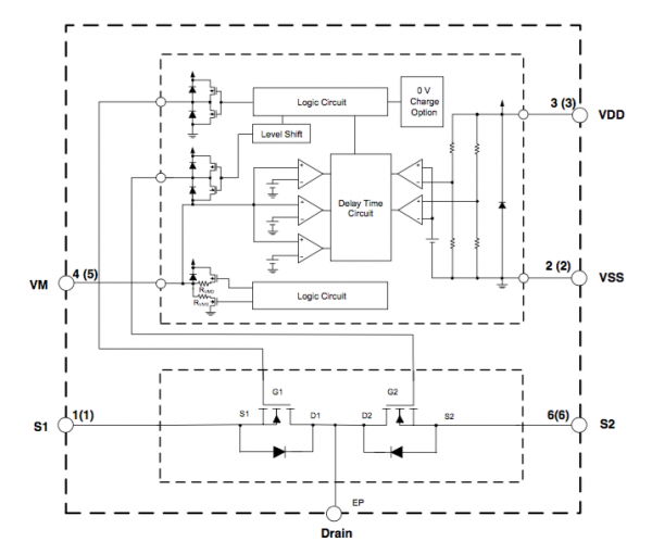
Figure 1. Functional block diagram of Diodes AP9214 battery protection IC
Manufactured on a high voltage process, the AP9214L has an absolute maximum rating of 24V but, as it is designed for portable devices, it also offers a very low quiescent current; typically just 3.0μA under normal operating conditions, dropping to as low as 0.1μA in power-down mode.
The voltage detection circuitry also offers excellent performance, between 3.5V and 4.5V in steps of 5mV with ±25mV accuracy. It includes overcharge and overdischarge hysteresis, with both charge and discharge overcurrent and overvoltage detection. A built-in fixed detection delay is also included and it is of course manufactured using a totally lead-free process and is fully RoHS compliant.
A typical application is shown in Figure 2. In normal operation the AP9214L controls battery charging and discharging by constantly monitoring the voltage levels of VDD and VSS while measuring the difference between VSS and VM. The battery is able to charge and discharge all the time the battery voltage remains between the overdischarge voltage level and the overcharge detection voltage level and the voltage on VM is between the charge overcurrent detection voltage and discharge overcurrent detection voltage.

Figure 2. Typical Applications Circuit for the Diodes AP9214 battery protection IC
As an example of operation, if the device detects a battery voltage in excess of the overcharge detection voltage for longer than the built-in fixed detection delay, it switches off the charging MOSFET and enters overcharge status. Once the voltage on the VM pin falls to below the discharge overcurrent detection voltage and the battery voltage drops to below overcharge release voltage, the device exits from overcharge status. This explains the Overcharge Status feature, one of the many modes of operation for the AP9214L - please refer to the AP9214L data sheet (http://www.diodes.com/_files/datasheets/AP9214L.pdf) for a full explanation of all operation modes and protection features.
The AP9214L is part of Diodes’ family of battery protection solutions (http://www.diodes.com/catalog/Battery_Protection_122), which also includes the AP9101C, the AP9211 and the AP9234L. The AP9214L, AP9234L and the AP9211L integrate dual N-Channel MOSFETs to offer a complete, single-chip solution, while all four devices feature a built-in detection delay timer, as well as Diodes’ powerful fault detection features.
Within this family, the AP9234L offers the highest accuracy; the overvoltage detection voltage is ‑15mV to +25mV with a ±12mV accuracy on the discharge overcurrent detection voltage, for example. However all four devices have been designed to meet the needs of OEMs developing portable devices such as Smart Phones and Wearable devices that operate from a single Li+ cell. Choosing any of these devices will provide significantly greater protection against common faults in devices powered by rechargeable battery cells.
Conclusion
Battery manufacturers provide documented operating conditions that must be met when implementing rechargeable cells in an end-product. Failure to meet these requirements can lead to catastrophic failure, most commonly accelerated by thermal conditions. Chemical-based rechargeable cells are enabled by a chemical process; a process that can reach uncontrollable acceleration under elevated temperatures. This can rapidly lead to unrecoverable failure or, in extremes, explosion and/or fire.
Many factors influence a cell’s operating environment, some of which can’t be controlled. But potential fault conditions such as overvoltage or overcurrent during charging, a short-circuit on the battery terminals or attempting to discharge the cell too rapidly can all be detected and controlled using a fully integrated single-chip solution such as those discussed here.
The demand for portable devices is only increasing and with that demand comes expectations, such as smaller devices, greater functionality and longer operational time on a single charge. Meeting these demands is putting pressure on battery manufacturers but, in turn, it is the OEMs developing the end-products that must ensure they are still safe and fit for purpose. By designing-in protection, those device manufactures can continue to meet the demand from existing and emerging markets for many years to come.