Driving The Digital Car With Analog Components
By: Chris A. Ciufo, Editor-in-Chief, Embedded, Extension Media Publishing
Today’s new cars get decent mileage, are relatively safe and are considered stylish, so auto OEMs must add something special to stand out. Car tech is the cornerstone differentiator of many automobile companies’ product offerings. Lately the “killer features” that consumers want and will pay extra for include tech packages such as: an in-vehicle infotainment (IVI) system with smartphone integration, rear seat LCDs, and all-around cameras for safety (Figure 1).
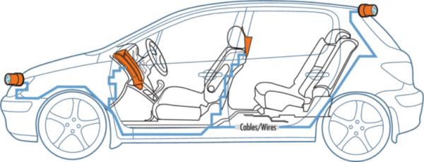
Figure 1: “Car tech” in the digital car includes center console and rear seat “infotainment” (IVI) systems, plus cameras for safety features. Note the labyrinth of cables and wires of often high-speed digital channels like PCI Express, Ethernet and HDMI.
This onboard embedded “infotainment” tech includes the digital standards designers are familiar with like USB, Ethernet, PCI Express, GPS and video decoders. And just like any other embedded system, designers are also finding the need to add analog components that:
- Recover clock signals and reduce timing jitter,
- Increase digital fanout and output drive capability, and
- Provide high precision clock sources in compliance to specifications like PCI Express.
Beyond these requirements, USB charging is becoming a “must have” feature. Finally, the digital car is also harsh environment. Certified, automotive-grade components are needed with long life cycles.
Let’s take a look at how the digital car mixes analog and digital devices in this evolving market.
Growing Market; New Challenges
The digital car is stuffed with systems running processors from Altera, AMD, ARM, Intel, Freescale, Hitachi, Renesas, TI, Xilinx, and others. Each of these is at the center of an embedded system with one or more LCD displays, PCI Express, Gigabit Ethernet, GPS, and USB I/O (Figure 2). Not surprisingly, these “car tech” embedded systems mirror those running a point-of-sale (POS) terminal, a gaming console, a mobile device, and a closed-loop servo system—all in a car.

Figure 2: The digital car’s embedded systems rely on analog components for clocks, data transmission and jitter improvement, and switches to improve fanout.
In other words: this is a typical, contemporary high-speed digital embedded system. There are challenges to provide: accurate timing (clock) generators for the processor/SoC and PCI Express (PCIe); maintain control of GHz signal jitter and “eye” margin; provide enough clock sources for all the peripherals; provide PCIe bridges and fanout; and maintain high quality video to/from remote sensors and displays. But different from other embedded systems, the digital car must also connect to and charge all of the driver’s and passengers’ high current mobile devices via USB.
The technical challenges here go beyond a “regular” embedded system because auto OEMs and their typical suppliers have not previously been expert in these kinds of high-speed, high data rate designs so it’s up to component suppliers to provide needed design expertise. And the car is a noisy EMI environment with long cable/wire runs that plays havoc on digital timing, as do the temperature extremes from winter to summer.
Re-Drivers to Drive Signals
Sub-micron leading-edge microprocessors, SoCs and FPGAs have limited output drive capability for long traces and inter-board connectors. In the high EMI environment of the digital car, long cable runs between boxed subsystems (or external cameras) further degrade signals through attenuation and noise. The end result is a closed “eye” for the very high speed signals—like PCI Express, USB, or HDMI—that define the latest digital car systems.
The solution to this problem is an active signal amplifier called a “redriver”. These marvels are designed to work with many different signal types, from PCIe to USB, HDMI and more. Redrivers at each end of a long signal trace or cable run return signals to within spec margins and are an essential part of the digital car (Figure 3).

Figure 3: A Redriver is a repeater/amplifier that cleans up attenuated and degraded signals. The open “eye” on the left is nearly closed (middle) as a result of the long trace or cable run. The eye is again open on the right and signals are returned to normal.
The Time is Right for PCI Express
Digital components, especially those driving multi-gigaHertz signals like PCIe, GigE or USB 3.0, require one or more highly accurate clock sources. IVI systems, with their emphasis on real-time graphics and video, have started to use PCIe for high-bandwidth I/O connecting peripherals and on-board SSD storage. Every PCIe device requires an accurate 100 MHz clock generator to create the ultimate 2.5 to 5.0 GHz data rates for Gen 2 and Gen 3.
A PCIe clock generator used in automotive applications will ideally provide several 100 MHz outputs to drive multiple PCIe devices and save board real estate. Having multiple outputs eliminates the need for clock buffers and their inherent timing latency. Compliance to PCI-SIG specs for G2 or G3 is a given, with jitter under 3.1ps in order to maintain PCIe margin in such a harsh environment. PCIe clock generators also need to be automotive grade and qualified to Automotive Electronics Council Quality (AEC) Q100 standard.
Having multiple outputs allows driving the processor or SoC and other PCIe devices since most processors don’t provide PCI clocks (Figure 3). An exception is Intel CPUs, but they consume two pins for the differential signal; this adds routing challenges for large pinout devices. Providing multiple outputs eliminates buffers, as mentioned, while saves money for auto OEMs building millions of units.

Figure 4: Typical use for a four-output (4) PCI Express clock generator in automotive infotainment.
The automotive grade Pericom PI6C557-03AQ/ PI6C557-05Q spread spectrum PCIe 2.0 clock generators, for example, drive two or four LVDS or HCSL outputs (25 MHz, 100 MHz, 125 MHz, or 200 MHz), have a phase jitter of 2.1ps that beats the PCIe spec, yet only require a low cost 25 MHz crystal next to the 16/20 pin TSSOP footprints. These particular PLL-based devices are interesting because of the multiple output frequencies, which allow designers to clock PCIe or Ethernet peripherals.
We’ve been describing how PCI Express is used as a common in-system communications channel between peripherals. In some cases, rear seat LCD subsystems may connect via PCI Express due to its high data rate. In other cases, PCIe may represent the only fast channel available in an era of SPI or I2C slow devices. In all of these instances, there’s a need to bridge a processor’s PCIe channel to multiple devices.
A PCIe (Packet) Switch bridges one PCIe channel to many, increasing a processor’s fanout. By adding intelligence to the bridge that chooses which packets to pass to what port, a simple one-to-many bridge becomes a packet switch. Qualified to AEC-Q100 (ICs) for automotive applications, this kind of intelligent bridging offloads the host CPU or SoC by allowing routing and communication decisions without processor intervention.
Crystal Clear Timing
Most digital systems maintain a real-time clock, but there’s one in an automobile that’s visible to the user: it’s in the IVI system. While this is only one of many RTCs in the car that rely on crystal oscillators (XO) as the base timing reference, the one in the IVI remains critical. This RTC displays time-of-day, and it awakens systems the driver cares about most—such as the instrument cluster, outside temperature display, or back-up camera.
By far the most common reference oscillator is the “32 kHz” XO (32.768 kHz) and it provides the base time reference for RTCs, processors in Sleep, and other peripherals. In multi-million unit automotive applications, the temptation is to use ultra low cost tuning fork-based XOs. While industry-accepted and proven, tuning fork XOs have two key attributes not suitable for a car’s IVI system: temperature drift and a very long start-up time.
Figure 5 shows the frequency drift (called “ppm”) versus temperature between the common tuning fork crystal (left) and the “AT Cut” crystal (right). For the tuning fork XO, a ΔT of -20°C results in a 160 Hz ppm, which can be substantial for RTCs and other timing solutions that require more precision, or whose PLLs can’t tolerate this much variation. The AT Cut crystal (“AT” refers to the 35.25 degree angle of the crystal cut) varies only +25 ppm over about 40°C. This is at least a 5x improvement in temperature precision.

Figure 5: Tuning fork XO (left) vs AT Cut XO (right). The tuning fork ppm (ΔF/F) varies greatly with temperature. AT Cut crystal oscillators from Diodes Incorporated, for example, exhibit the ppm frequency precision shown in the right-hand curve.
As well, tuning fork XOs take a long time to start up—as much as 1000 ms, compared to AT Cut XOs. Devices from Diodes Incorporated, for example, can start up in as little as 2 ms with a typical time of 10 ms. This makes a big difference in what the driver experiences if he/she is forced to wait several seconds as tuning fork XOs stabilize and a sequence of systems all boot up. The AT cut XO is the preferable choice.
Getting a Charge from Ubiquitous USB
No longer reserved for merely connecting peripherals like mice and keyboards to computers or synching an iPhone to iTunes, USB provides power to all kinds of consumer products. As mobile devices like smartphones and tablets migrate into the automobile, USB provides the umbilical cord for IVI connectivity and device charging while on the go.
The variations in USB for automobiles go beyond the data rates of USB 1.1, 2.0 and 3.0; in fact, there are various charging modes and current sourcing options, along with different international standards like Chinese Telecom Standard YD/T-1591. One key metric is the amount of current a USB connection can provide, from milliamps up to the 2.0A required by Apple’s iPad and many new Intel/Microsoft 2:1 devices. Consumers expect to use (and charge) all of these in their car.
Apple, for example, defines Apple-1A and Apple-2A communication modes in their USB chargers. This is why the smaller charger from an iPhone charges an iPad so slowly: not only is the source current different, but the charger knows this and adjusts the charge profile accordingly.
For the broader market, the USB Implementers Forum has defined the USB Charging Spec (USB Battery Charging 1.2) with multiple variations on a charging theme. Some of the modes are described in Table 1.
| DCP | Dedicated Charger Port | Used when enumeration is not available |
| CDP | Charging Downstream Port | Used when enumeration is available and FAST charging is requested |
| SDP | Standard Downstream Port | Used for systems with standard USB host ports |
Table 1: USB Implementers Forum (USB-IF) Battery Charging specifications (from their 1.2 compliance plan document October 2011).
Referring back to Figure 2, the automotive IVI embedded system needs to support USB data communication plus multi-device charging. This includes all USB-IF charging standards shown in Table 1, plus non-standard (although widely used) charging profiles such as Apple-1A and -2A. For future-proofing today’s IVI system with tomorrow’s unknown devices, USB chargers should also have programmable current output limits, run off of a single 5V DC-DC converter input, and be AEC-Q100 qualified for rugged automotive applications.
One device that meets all of these criteria is Diodes' PI5USB8000Q. It supports CDP for data and charge at 1.5A, SDP for data and charge at 500 mA, and DCP for 1.5A charging. The device also supports Apple-1A and -2A, and can determine when a device is plugged in (called PowerNAP) and ramp up the power. When a device is disconnected, current sensing will place the IC in a low power mode. This is important in always-on automotive “Power Port” (aka “cigarette lighter”) applications that are not disconnected when the ignition switch is off.
Driving the Digital Car
Digital technology is a key differentiator for automobile OEMs as they try to stand out from the crowd, and they’re rushing to add more IVI cabin tech with every model. As designers deploy more high-speed digital systems with standards like PCI Express, Ethernet, HDMI, USB and more, they’ll also need to add companion analog devices for timing, buffering, repeating, and redriving signals. As well, USB charging—in all of its flavors—is a “must have” with today’s car consumers.