
Protecting Vehicle Electronics from Reverse-Battery Connection
Author: Siva Uppuluri, Applications Engineer
During the life of the vehicle, its battery may need to be disconnected for maintenance work or to replace it if it has developed a fault. During reconnection it is possible to reverse the polarity of the battery connection, which can result in potential short-circuits and other problems with loads connected to the battery. Unfortunately, this issue isn’t entirely prevented by the mechanical design of different sized battery terminals or the use of prominent color-coding of cables, connectors and terminals. Consequently some form of electronic blocking or reverse-polarity voltage protection is necessary, not solely to safeguard the battery itself but to protect the ever-increasing number of electronic control units (ECUs) that modern vehicles rely on.
This article examines various approaches that can be used for reverse-battery protection and examines the advantages and drawbacks of each. In particular it looks the Super Barrier Rectifier (SBR®), which addresses the shortcomings of various MOSFET-based solutions and even out-performs the simple Schottky diode in terms of efficiency and ruggedness.
Potential Protection Circuits:
Popular methods for protecting ECUs include using a blocking diode or, to avoid the inefficiency of a regular rectifier diode, using an MOSFET as an ideal diode. Other solutions might use a purpose-designed IC. Ultimately the chosen solution has to meet the performance needed in the specific context of the end-application, considering factors such as component count/complexity, cost, energy efficiency and, probably most importantly, whether it adequately withstands the fault condition and any associated transients. The latter is usually assessed using ISO7637-2 defined pulses that test the compatibility of equipment installed in vehicles to conducted electrical transients, as described later.
A blocking diode is the simplest means of protecting against reverse-battery connection. Inserting a rectifier diode in series with the ECU load ensures current can only flow when the battery is correctly connected. Since no control signal is required, circuit complexity and component count are low. On the other hand, the diode dissipates energy all the time the ECU is powered, owing to its forward voltage, VF, which can cause significant losses in high-power applications.
Using a low-VF device, such as a Schottky diode, instead of a standard rectifier can mitigate the losses associated with a standard rectifier. However, the reverse-leakage characteristic of the Schottky diode is particularly dependent on temperature, resulting in increased energy losses and leaving the device vulnerable to thermal runaway if high reverse power is applied under high-temperature conditions.
Inserting a MOSFET in the high-side supply to the ECU and connecting the gate so that the device is turned on only when the battery polarity is correct is an alternative solution. Since the MOSFET on resistance (RDS(ON)) is typically only a few milliohms, I2R power losses are low compared to the loss incurred due to the diode VF. In addition, the reverse-blocking performance is more robust than that of a Schottky diode. An N-channel or P-channel MOSFET may be used, provided the device’s drain-source body diode is oriented to conduct current flowing in the correct direction into the ECU.
Either an N-channel or a P-channel MOSFET can be used for high-side reverse-battery protection. An N-channel device provides the lowest power loss topology by virtue of its low RDS(ON). However, a gate voltage greater than the battery voltage is needed to turn the MOSFET on. This requires a charge pump as shown in Figure 1, which increases circuit complexity and component cost, and can also introduce EMI challenges. A comparably sized P-channel MOSFET will have a higher RDS(ON) and hence higher power losses but can be implemented with simpler drive circuitry comprising a Zener diode and a resistor.
Although inserting the N-channel MOSFET in the low-side circuit would eliminate the need for a charge pump, it would also introduce a ground shift that is not acceptable for sensitive automotive systems.
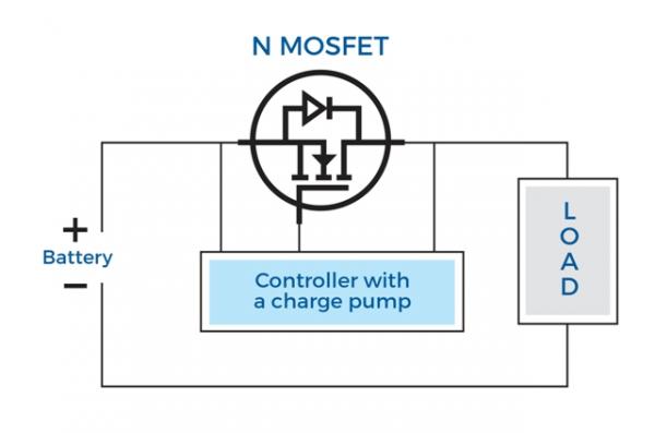
Figure 1a. The charge pump needed to supply the MOSFET gate voltage increases complexity and may introduce EMI issues.

Figure 1b: A P-channel MOSFET used for reverse-battery protection device requires fewer components but incurs higher power losses
The Super Barrier Rectifier, a proprietary rectifier technology from Diodes Incorporated, combines the simplicity and robustness of a conventional diode with the low forward voltage of a Schottky diode to provide a superior-performance solution to the challenge of reverse-battery protection. Figure 2 shows how the SBR is inserted in the high-side supply to the ECU, in much the same way as a conventional diode.

Figure 2. The SBR is connected in the same way as a diode or MOSFET, with no charge-pump circuitry required.
The Super Barrier Rectifier uses a MOS channel to create a low potential barrier for majority carriers. This results in a combination of low VF with high reliability, unlike the typical Schottky device. At the same time the SBR has lower reverse leakage, which remains stable even at high temperatures thereby minimizing energy losses and avoiding the risk of thermal runaway associated with Schottky diodes. Moreover, freedom from Schottky junctions also ensures higher surge tolerance. Also, the SBR avoids the charge pump required with an N-channel MOSFET, which means there are no EMI concerns.
Although designed to prevent current flow due to reverse-battery connection, the protection device can itself be exposed to potentially damaging transients. While numerous types of switching transients can give rise to pulses of short duration, the most dangerous high-energy pulses are.
ISO Pulse Testing:
Any solution designed to protect the vehicle’s battery from a reversed connection also needs to be robust enough to withstand switching transients such as the high-energy pulses caused by events such as sudden disconnection of the supply when powering an inductive load or by load dump, i.e. when the battery is disconnected while charging from the alternator.
Testing to meet the harshest of these conditions, when applied to circuits providing reverse-battery protection, is undertaken using pulses defined by ISO7637-2:
Pulse 1 represents the case of supply disconnection while powering an inductive load, where the rectifier is subjected to a high negative voltage pulse. The ISO defined pulse conditions are shown in Figure 3.

Figure 3. ISO Test Pulse 1 simulates a severe negative pulse caused by supply disconnection.
Apart from this pulse, Pulse 3a also subjects the device to high negative voltage, but the duration of this pulse is very low (0.1μs) and this pulse represents the switching transients.
These negative transient voltages temporarily subject the protection devices to an avalanche condition. A detailed description of an avalanche condition and its effects on the semiconductor junctions are beyond the scope of this article. However, in simple terms, when a PN junction is subjected to an avalanche condition, the junction breaks down and allows a large amount of reverse current to flow through it. Avalanche can cause irreversible damage if the device is not rated to handle the current and energy involved. In an automotive reverse battery protection application, these avalanche conditions occur due to the magnetic energy stored in inductive loads, such as relays, and any parasitic inductances, making it a limited energy event. Hence, if the device had an adequate avalanche rating it can survive these situations.
It essential to choose a protection device with well-defined and guaranteed avalanche specifications, such as the reverse protection SBR whose characteristic is shown in Figure 4. Based on the pulse waveform and conditions given in Figure 3, the peak avalanche power involved in the Pulse 1 test can be calculated as:
Pavalanche_peak = Vavalanche * Iavalanche_peak
where:
Vavalanche = US = 100V
and:
Iavalanche_peak = Vavalanche/Ri = 100V/10Ω = 10A
hence:
Pavalanche_peak = 100V * 10A = 1000W
However the figure that matters in withstanding the energy generated by Pulse 1 is the average power over the duration of the pulse, given by:
Pavalanche_average = 0.5 * Vavalanche * Iavalanche_peak = 0.5 * 100V * 10A = 500W
So, as the stated width of Pulse 1 in ISO7637-2 is 2ms, it can be seen from figure 4 that the avalanche performance of this SBR device exceeds this ISO7637-2 requirement. As the other negative pulse, pulse 3A, is a transient with duration of just 100ns, a device that complies with pulse 1 will also pass pulse 3A testing.

Figure 4: Pulse duration versus maximum avalanche power (for Diodes SBR30A60CTBQ device)
Figure 5 compares the avalanche capability of a 10A 45V SBR against two competitive Schottky diodes. As can be seen the SBR has an avalanche capability that is between 3 and 10 times better than Schottky technology. The SBR is therefore better suited to reverse battery applications where reverse avalanche conditions occur. With careful design avalanche ruggedness similar to SBRs can be achieved with MOSFET solutions too.

Figure 5. The SBR’s superior avalanche ruggedness compared to Schottky diodes allows the use of lower rated devices for greater efficiency.
Pulse 5a represents the condition of load dump that occurs when the discharged battery is disconnected while the alternator is charging it. This is the most severe positive pulse the device can see. The ISO7637 Pulse 5a definition is shown in Figure 6.

Figure 6. Knowing the device’s surge-current capability helps determine ISO 7637 Pulse 5a survivability.
Consideration of Pulse 5a leads to the conclusion that information about the forward surge current capability of the device is essential when choosing a reverse-battery blocking device. Datasheets for ACQ101 qualified SBRs from Diodes Incorporated include this information.
Finally, the thermal capability of the device has a direct impact on the device’s robustness to ISO pulses. Diodes Inc. offers SBR solutions in a variety of packages to suit the thermal performance and PCB space requirements of the application. Please refer to Diodes website, www.diodes.com, for more details on these packages.
Conclusion:
A number of approaches are viable when implementing required battery reverse-polarity protection for automotive ECUs. Designers need to take into account factors such as ECU power consumption and cost, to achieve an optimal combination of efficiency, circuit complexity, electromagnetic compatibility and ruggedness. The Super Barrier Rectifier, which has been developed for high-power, high-temperature applications such as automotive, provides a competitively priced alternative to the Schottky diode and can deliver greater efficiency and reliability in situations where low cost, low complexity and freedom from EMI issues, are priorities.
SBR is a registered trademark of Diodes Incorporated.